Get this file: https://www.printables.com/model/420062-raspberry-pi-mount-for-din-rail-bracket-fan-mount
Wanting to mount it however to this: https://aliexpress.com/item/1005002245769197.html
which has different mounting holes (47.5mm versus 52.5mm and, need to be for M4)
1.
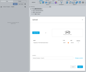
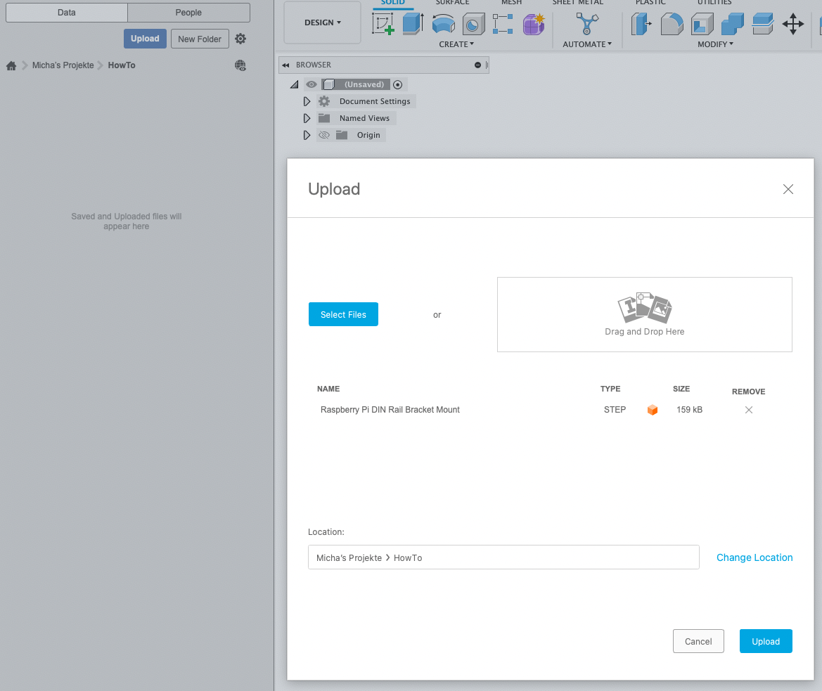
01 Upload STEP File 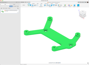
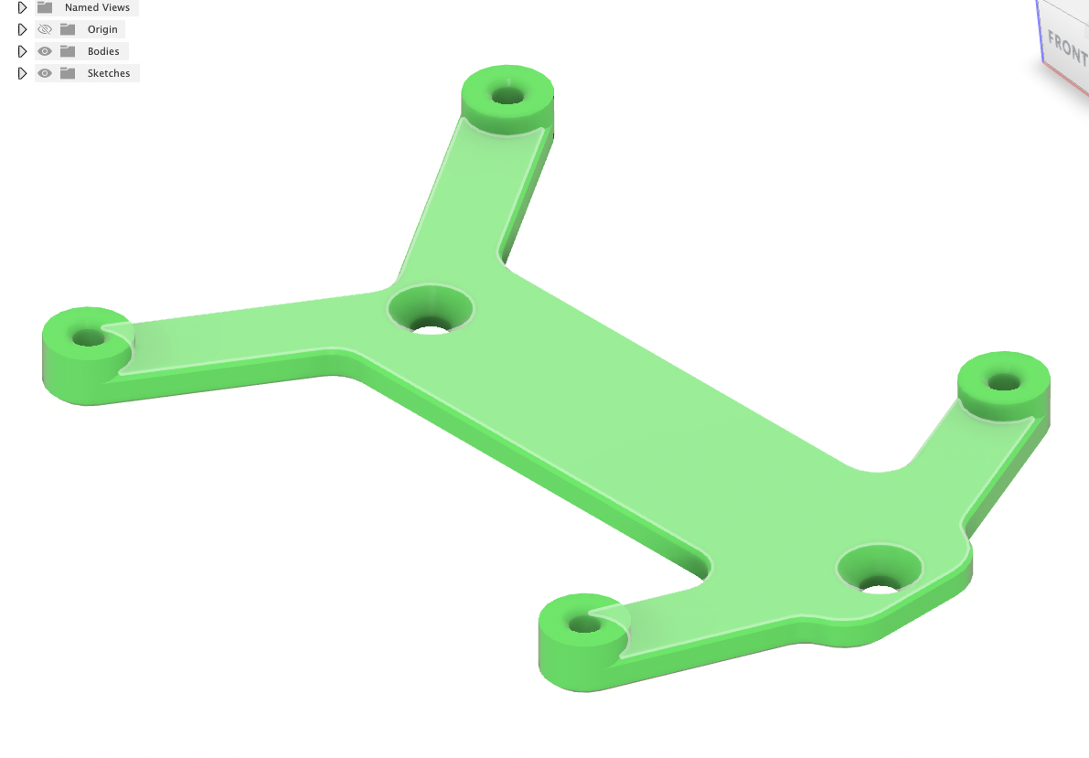
02 Open STEP File 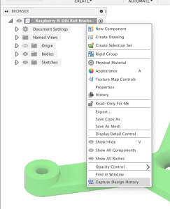
03 To be able to Redo / Undo better “Capture Design History 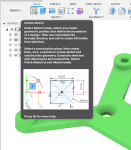
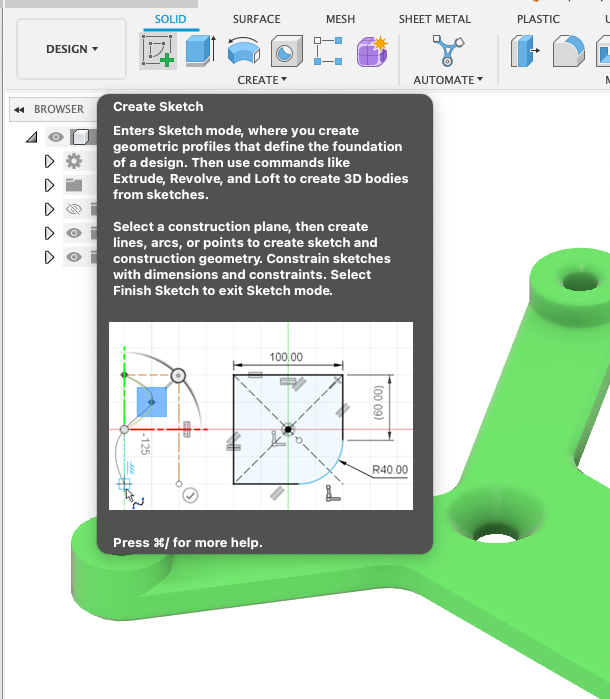
04 Create Sketch 
05 Choose the “Main Plane” 
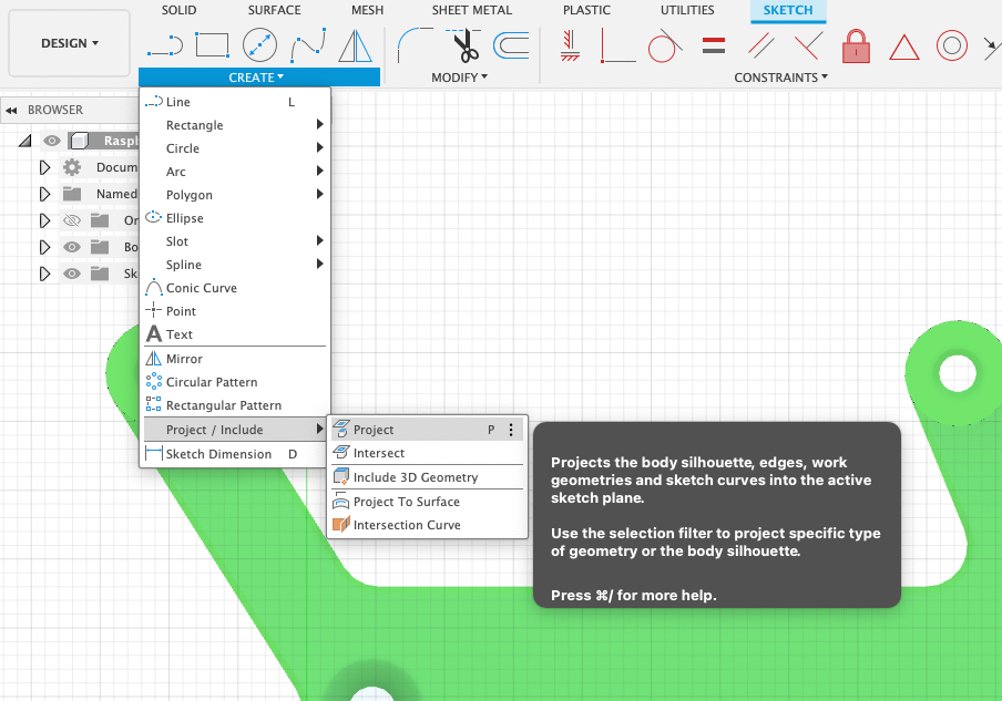
06 Create -> Project 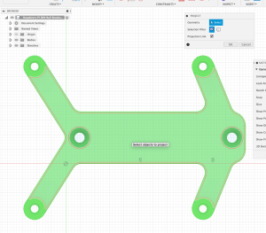
07 Select the same plane again 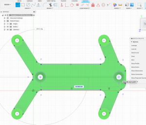
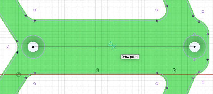
08 Select Line tool and draw a line between the 2 existing holes 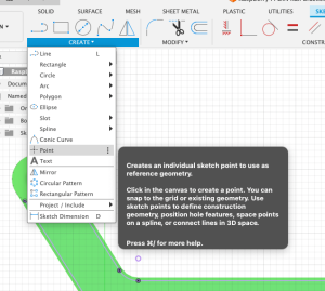
09 Create -> Point 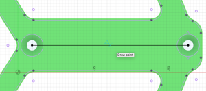
10 Move mouse on the line till a little blue triangle appears – this is the middle of the line. Click to draw a point.


2.
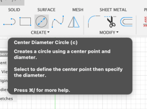
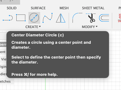
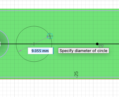
11 Create -> Circle 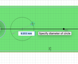
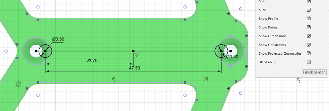
12 Draw 2 circles on the line. One left of the point you created and one right. Diameter set to your needs. For example 4.5 for M4 screw. 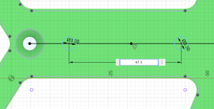
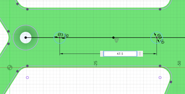
13 Press “D” for Dimension or choose Dimension from menu. Click on both circles and set distance to 47.5 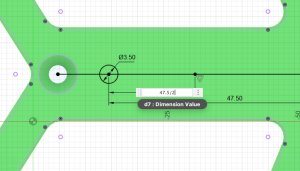
and set distance to 47.5 14 “D” for Dimension. Click on one circle and on the Point we created and set distance to “47.5 / 2” that point is in the middle of circles. 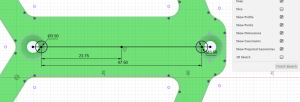
15 Sketch should now look like this 
16 Finish sketch 
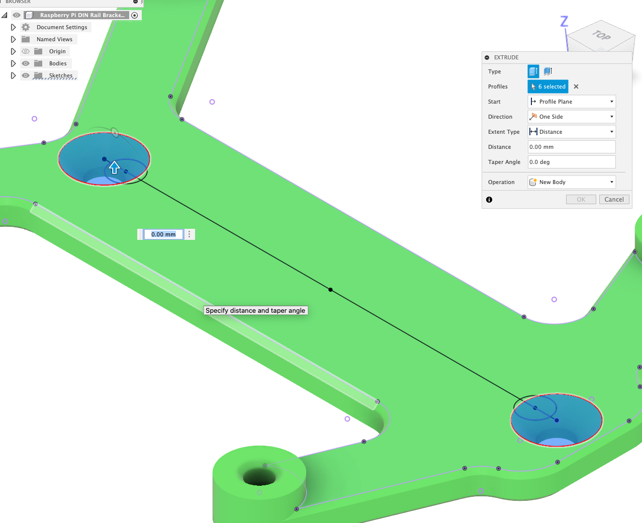
17 “E” for Extrude and select the Area where the original hole is 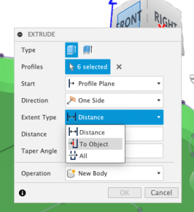
18 Extent Type “To Object” 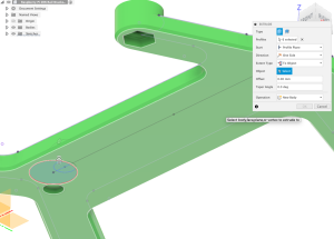
19 Flip the model and select the bottom plane 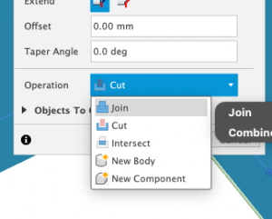
20 Operation “Join” to close the whole. Standard would be cut because Fusion thinks you want to cut.


3.

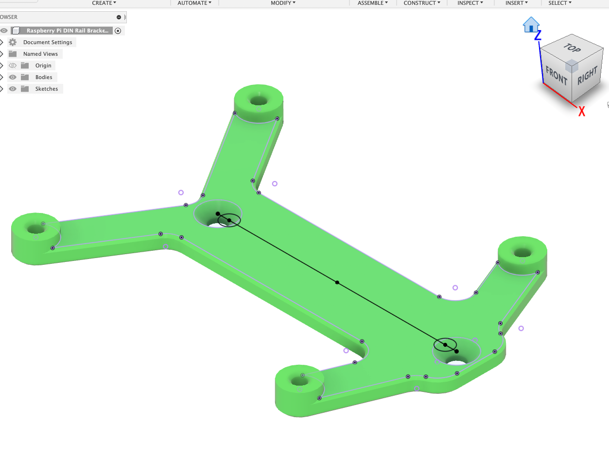
21 Model should now look like this. 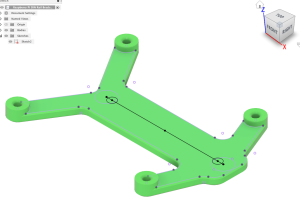
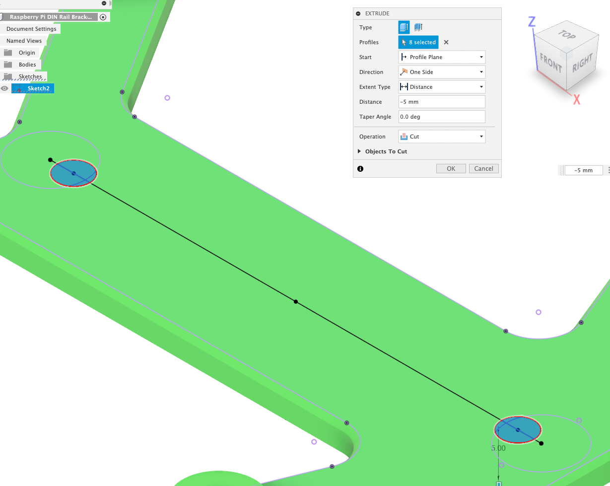
22 View the sketch we draw again 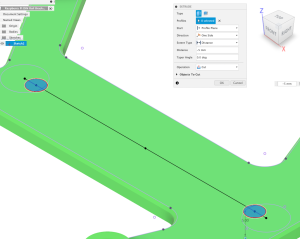
23 “E” for Extrude and select the areas where you want the holes. Distance -5mm. Operation Cut. 
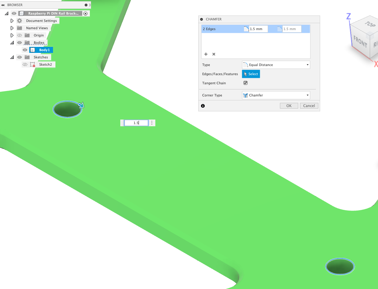
24 Select Chanfer tool from menu and select the upper edges from the holes. For M4 chamfer would be 2mm. 
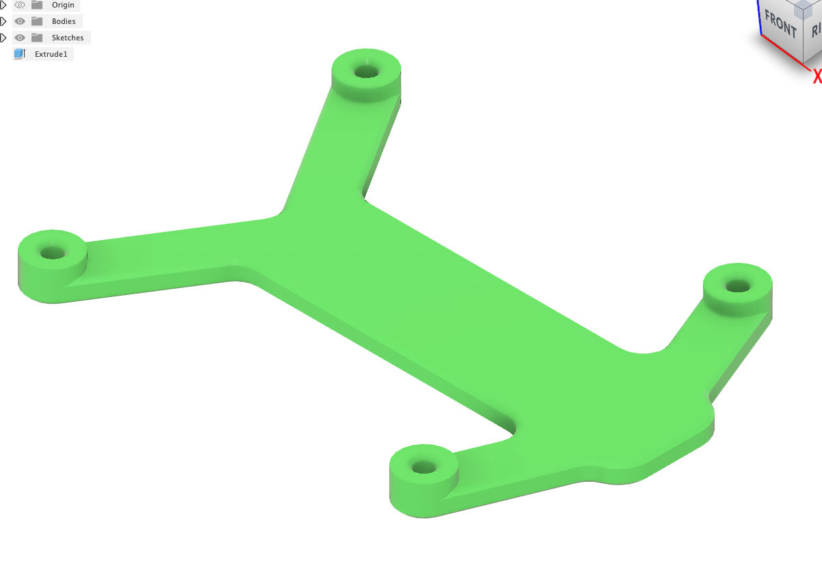
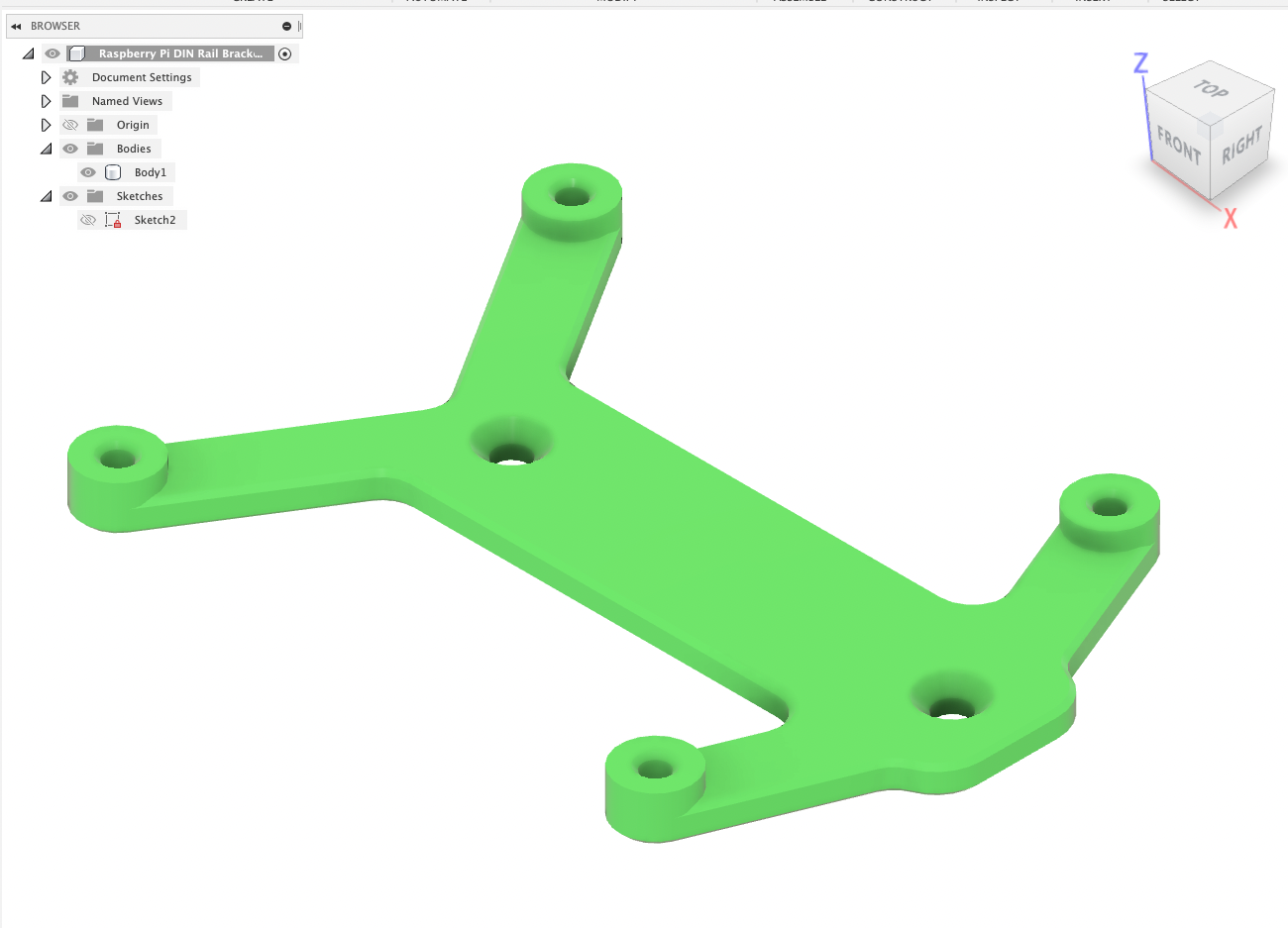
25 Finished part 
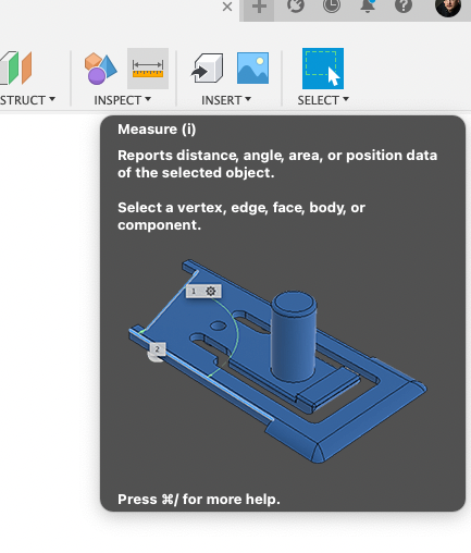
26 To Doublecheck Inspect -> Measure 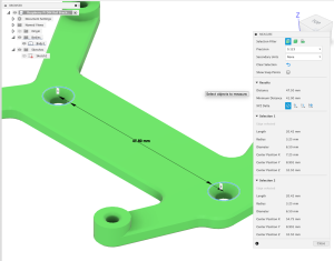
27 Select the holes. Distance should be 47.5


Huge thanks to Michael Mueller for his screenshots and write-up:
01 Upload STEP File
02 Open STEP File
03 To be able to Redo / Undo better “Capture Design History
04 Create Sketch
05 Choose the “Main Plane”
06 Create -> Project
07 Select the same plane again
08 Select Line tool and draw a line between the 2 existing holes
09 Create -> Point
10 Move mouse on the line till a little blue triangle appears – this is the middle of the line. Click to draw a point.
11 Create -> Circle
12 Draw 2 circles on the line. One left of the point you created and one right. Diameter set to your needs. For example 4.5 for M4 screw.
13 Press “D” for Dimension or choose Dimension from menu. Click on both circles and set distance to 47.5
14 “D” for Dimension. Click on one circle and on the Point we created and set distance to “47.5 / 2” that point is in the middle of circles.
15 Sketch should now look like this
16 Finish sketch
17 “E” for Extrude and select the Area where the original hole is
18 Extent Type “To Object”
19 Flip the model and select the bottom plane
20 Operation “Join” to close the whole. Standard would be cut because Fusion thinks you want to cut.
21 Model should now look like this.
22 View the sketch we draw again
23 “E” for Extrude and select the areas where you want the holes. Distance -5mm. Operation Cut.
24 Select Chanfer tool from menu and select the upper edges from the holes. For M4 chamfer would be 2mm.
25 Finished part
26 To Doublecheck Inspect -> Measure
27 Select the holes. Distance should be 47.5