Single, dual or triple screw Z?
(Part 1)
You will probably notice that most high-end commercial printers use either single or dual lead screws (or ball screws) but seldom 3.
Single screw Z pros
With just a single Z screw there is the least chance of mechanical quarrel. Mechanical quarrel is when two mechanical forces oppose each other and in kinematic systems it usually leads to increased friction or binding if the systems don’t have some compliancy built in.
With a single linear motion system there is only one linear path that the bed should move in. Normally two large diameter heavy duty *smooth rods or a single very wide linear rail are used to create the vertical linear motion system. If two smooth rods are used a single piece bed arm (or cradle) bridges both smooth rods and the screw lifts in the centre of this arm.
A single piece non moving bridge is located at the bottom and often another is place at the top, providing a very rigid mounting structure for the smooth rods capable of overriding any lateral forces a bent lead screw might impart to the bed arm. The lead screw will typically be loosely constrained at one end.
This setup provides a precision of movement and helps produce high quality prints.
There is almost no chance of lead/ball screw induced artifacts.
Nice open access to the bed without obstruction from multiple linear motion systems.
Very simple system.
*In some rare instances two widely spaced linear rails may be used but dual linear rails abut to prevent binding dual linar rails need to be aligned in multiple planes. This normally requires a finely machined surface for both rails to sit on (expensive) or some compliancy need needs to be built in (sub optimal).
Single screw Z cons
Can’t do automatic bed levelling. Bed levelling must be manual.
As the bed is always cantilevered and there is only one bed arm. This bed arm must be sturdy. This generally necessitates it being machined from metal (expensive).
The vertical linear motion system is normally bespoke and the bed arm and supporting structures (for twin smooth rods) are machined from billet for rigidity and accuracy….and hence consequently expensive.
Heavy duty linear bearings are required as they need to cope with the angular loads of the cantilevered bed. All else being equal these bearings also need to be longer for this reason than bearings used on dual or triple screw Z motion systems.
As the bed is only supported on one side it must be thick enough not to flex…which makes in expensive and heavy.
Z movement speed is usually limited to stop the bed ‘flapping’. If you are using Z hop when printing to stop the nozzle dragging across the just printed layer this will increase print times more than you might initially expect.
Bed depth is normally limited, and it is common that the beds will be much wider than they are deep.
As only one screw is doing the lifting it needs to be heavier duty than a two or three screw system and is hence often a ball screw. Ball screws are more expensive than leadscrews.
Summary
A single screw Z motion system with a cantilevered bed is the simplest solution and works great for small bed sizes.
However, to do a cantilevered bed properly you need expensive components and typically a custom machine bed arm, but the reward is a precision motion system without mechanical quarrel or screw induced artifacts in the prints.
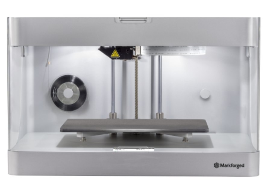
Single Z screw cantilevered bed systems are currently the most popular of the designs used in small format commercial printers.
Example below is of a MarkForged printer which is has excellent kinematics and is capable of producing very high quality prints.often
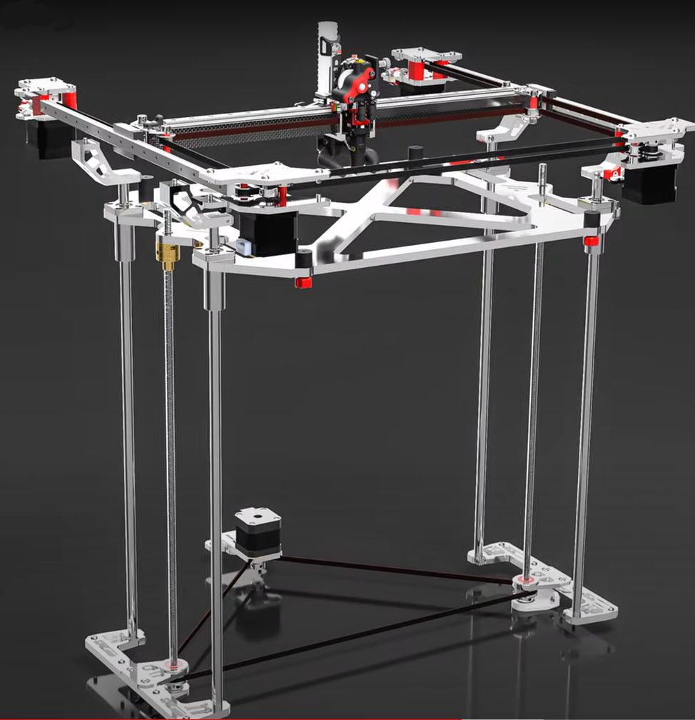
(Part 2)You will probably notice that most high-end commercial printers use either single or dual lead screws (or ball screws) for Z motion but seldom 3.Dual screw Z motion systems are also used in high quality prosumer kit printers like the VzBot.Dual screw Z motion systems are the most common in larger format commercial printers for good reason. Why?Dual Screw Pros
Dual screw Z motion systems are very similar in construction to that used for the single Z linear motion system-but of course, use two linear motion systems one positioned on each side of the bed. Each linear motion system consists of a single screw and a pair of smooth rods (Linear rails are almost never used in a dual screw system – because aligning them perfectly in all required planes would be very difficult.)
Typically, both leadscrews (or ball screws) are driven by a single Z motor via a belt and pulley arrangement, but there are also printers that use separate Z motors for each of the two Z screws.
This allows you to have large well supported beds and fast Z motion without risk of the ’flapping’ that could occur in a single screw cantilevered bed system talked about in Part 1 of this series of articles.
As a result being supported on both sides, all else being equal, the bed can be of a lighter/thinner and cheaper construction.
This is also true of the linear bearings which may be of lighter duty and more compact size than those used a single screw cantilevered bed setup.
…and of course the lead screws and ball screws can also be of lighter duty and lower cost.
A very stable bed also provides a foundation for very precise high quality prints.
And being very stabled, once the beds have been manually levelled they only need periodic relevelling.
Dual screw Z motion system cons.
There is some chance of mechanical quarrel between the two linear motion systems. The two linear motion systems must be precisely vertically aligned with each other or their needs to be some compliance in the system (which introduce imprecision to the printer).
Unlike with a single screw Z motion system if the linear motion systems are not perfectly aligned the bed now has two (rather than one) possible vertical paths, one at each side of the bed that can be minutely different from each other.
If the two Z linear motions systems are not perfectly aligned with each other this can cause artifacts in the print.
To obtain and maintain perfect alignment you now need a more rigid chassis and for this reason commercial grade dual screw printers are normally fabricated from sheet metal rather than the ‘stuck together sticks’ construction in many kit printers, where Aluminium extrusions are screwed together to provide the frame structures for the Z linear motion system. However, mass producing a printer from sheet metal is cheaper on than constructing it from individual extrusions, so this is no cost penalty.
The vertical linear motion systems are again normally bespoke and the bed arms or bed cradle and supporting structures (for each pair of twin smooth rods) are machined from billet for accuracy….and hence consequently expensive. All else being equally they do not need to be as rigid though as the assemblies used in single screw cantilevered bed systems.
Again as with the single screw Z motion system you can’t do automatic bed levelling. Bed levelling must be manual. But provided the supporting structures are robust enough this may only need to be done on initially set up and periodically thereafter.
Cost. A there are two linear motion systems you have double the number of components in the A motion system.
A dual screw Z motion system can support a large bed and providing a precision and very stable Z motion system. For these reasons is currently the most popular arrangement in larger format commercial printers.It may be the best compromise of all systems. Its only disadvantage over a three screw system is that manual bed levelling is required. But as mentioned before because these setups are very stable, bed levelling may only be required every few months.Image of the very nicely executed two screw Z design on the VzBot printer.
(Part 3)The next part of this series, (Part 4) will discuss triple screw Z motion systems, but before I get on to that I must discuss how to handle the thermal expansion of the printer bed as it heats up and its subsequent contraction as it cools down after printing.
As the bed heats up it will want to expand. Some mounting mechanism or compliance is required in the mounting to allow for this….as the Borg say resistance is futile.
If the bed is rigidly constrained at the edges the bed will be forced to bow between the mounting points as it expands.
Of course, this is not an issue with single screw Z system with a cantilevered bed, where the bed is only attached to the lifting mechanism on one edge.
There are several approaches to dealing with this. The simplest way to accommodate this is just to have some compliancy in the bed mounts. This is the approach adopted by many dual screw Z systems where the bed is attached on two sides. Even on triple screw printers like the Voron Trident, with relatively small print beds this approach is simple and works well enough.
Another popular mounting option for coping with thermal expansion/contraction of the bed is to what is often referred to as ‘”kinematic mounting’.
At this point I feel compelled to stand on my soap box and rant a little.
‘Kinematic mounting’ is a nearly meaningless term in this context.
According to the Britannica: Kinematics is the branch of physics concerned with the geometrically possible motion of a body or system of bodies without consideration of the forces involved.
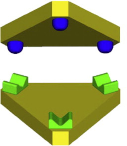
What people are really referring to are Kinematic Couplings.
According to the good folks at Wikipedia. Kinematic Couplings describe fixtures designed to exactly constrain the part in question, providing precision and certainty of location. Common Kinematic couplings are Maxwell and Kelvin couplings.
But while the bed mounting systems that I first saw appear on printers such as the Jubilee (others may have been first) and were subsequently adopted by Rat Rig V-Core printers and others, have some of the trappings and appearance of Kinematic couplings they don’t really fit the criteria of true Kinematic Couplings.
They are not true kinematic couplings because the individual locating constraints on printers such as the V-Core 3 are mounted on individual bed arms, that are in turn mounted on individual extrusions that are not rigidly indexed to each other and can all move individually with respect to each other, and hence precision and certainty of location cannot be assured. Consequently, I will refer to them as ‘pseudo kinematic coupling’ systems from this point on in these articles.
For the avoidance of all doubt, normally the two sets of mating components in a Kinematic Coupling are each mounted on a single rigid monolithic plate as per the diagram below, and this assures precision and certainty of location.
….Ranting over ….for the moment (Warning…. I am prone to rants).
However, the true purpose of these pseudo kinematic coupling systems in these printers is to provide a mounting system that allows the bed to be attached on more than one side and expand when heated without bowing and they do this admirably well
(Unfortunately these pseudo kinematic coupling systems also introduce a lot of issues that I will address in part 4.)
They also provide for a freedom of movement around the X and Y axis (roll and pitch) which is very useful if you want to implement auto tilt bed levelling functions.
Anyway back to the current story…
Wanted and unwanted degrees of freedom of movement.
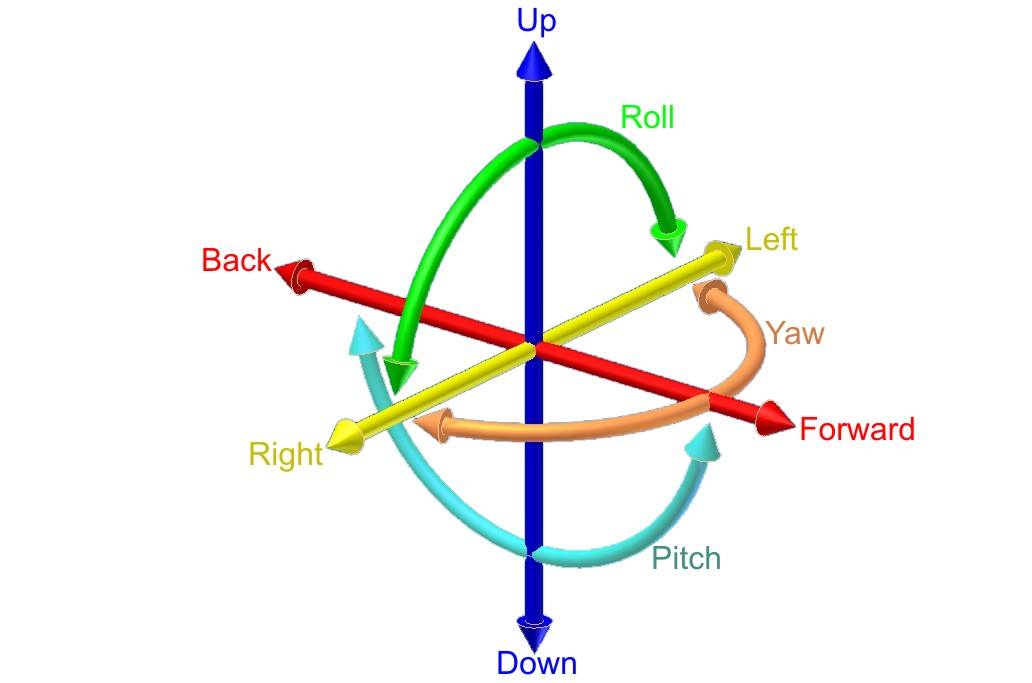
Any fully unconstrained object has what are call six degrees of freedom. If we imagine a bed floating in the International Space Station. It has the following six degrees of freedom that it can move in if there is a disturbing force:
1. Movement in the X direction, (left, right).
2. Movement in the Y direction, (back, forward).
3. Movement in the Z direction, (up, down).
4. Rotation around its Y axis, (roll).
5. Rotation around its X axis, (pitch).
6. Rotation around its Z axis, (yaw).
In a 3D printer Z motion system, disturbing forces can be due to bent or misaligned leadscrews (or ball screws), linear rails or smooth rods, external vibrations or from vibrations caused by a fast accelerating print head.
If all the bed arms on these printers are fully constrained by wide high precision linear guides mounted to solid structures, the beds undesired movements would be nicely constrained, and the desired movements would be nicely unconstrained ..excellent. Unfortunately this is not the typically the case.
In single and dual screw Z motion systems as previously discussed in Part 1 and Part 2 of this series of articles, the movement of the bed arms is typically precisely controlled, by widely spaced, sturdy smooth rods (or wide and expensive precision linear rails) and bed arms that span these. These mechanisms are strong enough to resist the wayward intentions of bent lead screws (and ball screws), external vibrations or vibrations caused by a fast accelerating print head and consequently the bed is very stable and follows a tightly constrained vertical path.
Tragically in triple leadscrew designs this is not generally the case, and the bed arms are not precisely controlled and this leads to visible Z artifacts in the prints.
Part 4 will discuss triple screw Z systems in more detail. Part 4 is where this series of articles gets really interesting, but I had to cover this groundwork first.
Part 5 will look at the issues introduced in this this article and some more that will be introduced in part 4 with regard to triple screw Z motion systems currently being used in printer designs.
Part 5 Will also introduce one of several possible solutions for completely solving these issues including the 1P Z motion system.
Maxwell kinematic coupling image from sciencedirect.com
Six degrees of freedom diagram from Wikipedia.
(Part 4)Many kit 3D printers use Triple screw Z motion systems. There are only two reasons a designer would want to do this and several reasons not to.The advantages of a Triple Screw Z motion system1. Cost, unlike single and dual screw Z motion systems, this option doesn’t require expensive machined bed arms (or cradles). It can be assembled with inexpensive off the shelf components and printed parts, which is no bad thing.2. It allows printer designers to implement automatic Z tilt bed levelling. This convenience is the key reason why hobbyists are very keen to have three screw Z motion systems. Although as you will see, maybe we should be more careful of what we wish for.
Now’s a good time to differentiate between, Mesh Bed Levelling and Z Tilt Bed Levelling which are two different things. Nearly all modern printers offer both:
1. Automatic Mesh Bed Levelling/compensation.
2. Z Tilt Bed levelling which can be either manual or automatic. Only triple screw Z motions systems with three separate Z motors can do automatic Z tilt bed levelling.
Automatic Mesh Bed Levelling is used to compensate for the fact that no bed will be perfectly flat across its entire surface. Typical variances across the full range of the bed are in the range of 0.05 mm to 0.5 mm.
Automatic Mesh Bed levelling is achieved by using a sensor attached to the print carriage to measure the distance between the printer carriage and many specific points on the bed. The sensor measures the gap between the printer carriage and the bed at multiple points and stores these values.
These measured values are then used to calculate how much to minutely raise and lower the bed as the print head travels across the bed while printing the first layer, to achieve an even thickness first print layer that adheres well to the bed. This automatic mesh bed levelling/compensation is typically gradually reduced layer by layer over the subsequent 10 layers until there is no mesh bed compensation.
Z Tilt Bed Levelling is the process of making the bed as level as possible to the XY plane that the print head moves in.
Manual Z tilt bed levelling is normally used on printers using single and dual screw Z. It is typically achieved by manually adjusting screw height adjusters between the printer bed and the cradle it sits on. The distance between the nozzle and bed is often gauged by sliding a piece of paper between the nozzle and the bed and testing multiple points across the bed until the user decides the best approximation of level has been achieved. With a stable setup it doesn’t need doing before every print and may only need to be done every few months.
Automatic Z Tilt Bed Levelling
Is done by using the same senor used for Mesh Bed Levelling to measure the height of the bed at three prescribed points. Typically it uses only three points on the bed for this process, as three points on a *perfectly flat bed can describe a plane.
Automatic z tilt bed levelling can only be done on a printer with a triple screw Z motion system. Once the printer knows the value of the three points it drives the individual motors that turn the three Z motion screws to adjust the roll and pitch of the bed to get it flat to the best of its knowledge….which is convenient and looks very cool in action and is also a great marketing too.
*Note in the paragraph before the one above, I said ‘perfectly flat’ bed. If the bed is not perfectly flat and one or two off the three measurements is taken is in an outlier ‘hollow’ or ‘hill’ on the bed, then the subsequent bed levelling will not be a good approximation. It would be better if automatic bed levelling was done by calculating mean values from the multiple height points already acquired from the Automatic Mesh Bed Levelling, but I do not know of any printer firmware doing this yet.
When doing manual bed levelling you are more likely to take in a greater range of sample points and ignore outlier values to achieve better bed levelling and for this reason manual bed levelling can be superior to automatic be levelling.
The disadvantages of a Tiple Screw Z motion system.
Triple Z motions system usually result in a less stable bed and hence Z tilt bed levelling is typically required and built into the start routine of every print. This increases the start time for every print.
Triple screw Z motion systems also come with an increase in design complexity, requiring more complex interactions between more parts as we will see shortly.
A lot of this extra complication is required to ensure that the bed does not move in the unwanted degrees of freedom of movement (discussed in Part 3 of this series of articles). As a reminder the unwanted degrees of freedom of movement are:
1. Rotation around the Z axis (yaw)
2. Movement in the X direction (left and right)
3. Movement in the Y direction (front and back)
Any movements in these unwanted directions will lead to inaccuracy of layer stackings and cause unwanted artifacts in the print.
Many of these triple Z designs do not address these unwanted degrees of freedom of movement very well. One notable exception I can think of is the Hevort design.
OK it’s time to look at the kinematics of Triple screw Z motion systems.
The simplest triple Z motion system is that used on printers like the Jubilee and subsequently adopted by the Rat Rat Rig V-Core 3.
These printers have three lead screws each partnered with a single linear rail. A bed arm is screwed to each of the three carriages that run up and down the three linear rails to create three independent Z linear motions systems used for moving the bed in the Z direction.
This simple design has several flaws.
1. It is impossible to align all three linear rails perfectly with each other. Hence the bed has three different guiding paths it should take, none of which quite agree with the other. If there was not some compliancy (clearances) between the carriages and the rails there would be mechanical quarrel and the binding. The design would work perfectly if the three vertical motion systems could be perfectly aligned, and these clearances were not required.
2. The least expensive and easiest way to achieve the clearances required to prevent this mechanical quarrel is to use relatively narrow 9 mm (MGN9) linear rails or narrower. This allows the individual bed arms to rotate slightly on the linear rails which means the bed arms can all move in a narrow arc. This means they are better described as linkages (rather than fixtures) between the linear rails and the bed and this allows the bed to both move in the X (left right), Y (forwards, backwards) directions and rotate around the Z axis (yaw).
3. Compounding these issues is that the connection between the bed and bed arms is a spherical ball sitting between two parallel metal pins in a pseudo Maxwell Coupling arrangement (See Part 3 for more details on why this is not a true Maxwell Coupling). The spherical ball can both slide along the pins and rotate.. Spherical balls are used to allow the bed to rotate around the X axis (pitch) and Y axis (roll). If the bed could not pitch and roll it would be possible to have an automatic Z tilt function. But unfortunately, the selection of this bed to arm connection also allows the unwanted degrees of freedom of movement in X (left and right) and Y (forward and back) directions and rotation around the Z axis (Yaw) in this arrangement.
These factors combine to allow what I describe as a hula movement if there are disturbing forces. You can see this ‘hula’ motion in the animation below.
4. If there were no disturbing forces all of this would be of no issue. However, there are a number of disturbing forces and the forces that are imparted to the bed arms cannot be constrained by the linear rails, due to the required clearances (between rails and carriages) discussed above or the selected connection between the bed arms and the bed as also discussed above (spherical balls sliding and rotating in pins).
The main disturbing forces are.
i) Vibrations and resonances imparted to the frame and bed by the rapidly moving print head.
ii) The print head dragging across the bed (on the first layer) and on subsequent layers the previous printed layer. Surprisingly I was able to isolate and observe movement in the bed caused by this in some of my testing.
iii) Lead screws that can never be perfectly straight cause unwanted movement in the bed arms. This is possible because the bed arms are free to fractionally move due to clearances between the rail carriages they are attached to and the linear rails.
(Ball screws will typically be straighter but are also never PERFECTLY straight.)
iv) Lead screws that can never be perfectly aligned to the stepper motor shafts due to imperfect couplers. (However, as these couplers are machined parts, high quality options while not perfect can be pretty good.
v) Stepper motor shafts that can never be perfectly aligned to the linear rails, particularly so because the stepper motors are often mounted in printed plastic parts and are often mounted to different physical elements of the printer than the linear rails.
Vi) Leadscrews (and ball screws) can never be perfectly alighne to the linear rails. This misalignment causes mechanical quarrel between the lead screw and it’s corresponding linear rail. This is further exasperated by misalignment between all three sets of Z motion systems. It is impossible to expect to achieve perfect alignment between all six elements, three linear rails and three lead screws. Wherever you have mechanical quarrel you generally have binding, increased friction and stiction combining to provide uneven and unpredictable motion.
It’s not all bad news
With careful tuning and some luck on a good day, it is possible to get reasonable quality prints, with the configuration I have described above, but finding consistency and achieving precision layer stacking with this set up is not possible without upgrading the design.
The key advantage of the Triple Screw Z system is that it uses inexpensive components that can be purchased off the shelf and does not need the expensive custom machined parts of a good dual screw Z motion system.
It is also possible to upgrade the kinematics and as I mentioned previously there are some notable exceptions that address the issues correctly.
In Part 5
In part 5 will discuss some of the upgrades that can help mitigate, but not completely resolve these issues, such as Wobble Rings, Oldham couplers and VenterMechs.
Part 6 In Part 6 of this series of articles, I will talk about how some of the existing Triple Z designs don’t have any of these issues and also propose a new solution, the 1P Z motion system that I am currently testing that addresses all of the root causes of these issues to combine the best features of a dual screw Z systems precision and the convenience automatic Z tilt. I will also point out why even the 1P Z motion system is still not a perfect system.
The animation below shows the unwanted ‘hula’ movement. The movement in the animation is much greater than that in practice (for illustrative purposes), because in practice the rail carriages that the bed arms are bolted to can only rotate fractionally on the linear rails. But when we are dealing with a desired accuracy of less than 0.05 of a millimetre of variance between layers, even fractions of a degree of rotation between the linear rail carriages and the linear rails is enough to cause visible artifacts in the prints.
(Part 5)In Part 4, I discussed how the bed arm and mounting systems for print beds (in most common implementations of a triple screw Z printers) do not constrain the unwanted ‘hula’ movement of the bed caused by disturbing forces. As shown in Part 4 of this series of articles this ‘hula’ movement causes unsightly artifacts in the prints.To recap these main disturbing forces were listed as:i) Vibrations and resonances imparted to the frame and bed by the rapidly moving print head.ii) The print head dragging across the bed (on the first layer) and on subsequent layers the previous printed layer. Surprisingly I was able to isolate and observe movement in the bed caused by this in some of my testing.
iii) Lead screws that can never be perfectly straight cause unwanted movement in the bed arms. This is possible because the bed arms are free to fractionally move due to clearances between the rail carriages they are attached to and the linear rails. (Ball screws will typically be straighter but are also never PERFECTLY straight.)
iv) Lead screws that can never be perfectly aligned to the stepper motor shafts due to imperfect couplers. (However, as these couplers are machined parts, high quality options while not perfect can be pretty good.
v) Stepper motor shafts that can never be perfectly aligned to the linear rails, particularly so because the stepper motors are often mounted in printed plastic parts and are often mounted to different physical elements of the printer than the linear rails.
vi) Leadscrews (and ball screws) can never be perfectly alighned to the linear rails. This misalignment causes further mechanical quarrels between the lead screw and their respective linear rails.
This is further exasperated by misalignment between all three sets of Z motion systems. It is impossible to expect to achieve perfect alignment between all six elements, (three linear rails and three lead screws). Wherever you have mechanical quarrel(s) you generally have binding, increased friction and stiction combining to provide uneven, inconsistent and unpredictable motions.
Early attempts at solving the Hula movement issue.
Up until now most attempts to rein in the ‘Hula’ movement of the bed and reduce the consequent print artifacts have focused on decoupling unwanted lateral movement of the Z leadscrews (or ball screws) from the bed arms.
Oldham Couplers.
Oldham couplers are normally used for connecting too shafts together. They provide tolerance for misalignment. When installed between the leadscrews (or ball screws) and the body of printer arms they can perform the function of ‘de-couplers’. These were the first solutions many people and some manufacturers played with.
Unfortunately, Oldham de-couplers have more friction than other screw de-couplers. I will come back to why low friction is so important in a minute.
Wobble Rings.
The second attempt I saw to do this were the wobble wings employed on the Hevort printer and later wobble ring implementations.
I experimented with the wobble ring design and released a version for the Rat Rig V-Core 3 printers about a year ago. A number of people used my iteration of the wobble ring design and were very happy with the reduction in lead screw induced artifacts in their prints.
My design was built upon previous work done by MirageC of Hevort fame, Spiro Argyros and collaborated swapped notes gentleman on discord who uses the pseudo name, ‘r0bb10IT’.
I won’t go into the wobble ring design in detail but Wobble Rings are essentially Oldham couplers with bearings to lower the friction.
In my implementation I integrated the top wobble ring into the bed arms (as previously done by r0bb10IT) and integrated the leadscrew thread directly into the middle ring. This integration provided a more compact assembly (preserving Z range) and a simpler design with less parts and worked very well.
But while this design worked very well to reduce lead screw induced print artifacts, the design was still complex and made working on and servicing the printer more time consuming.
Details and files for these can be found here: https://www.thingiverse.com/thing:4975400
The search for a better solution.
In the search to reduce the complexity of wobble Rings and improve the performance of Oldham couplers I experimented with a variety of low friction materials to attempt to reduce their friction, including Ptfe (Teflon) and Uhmwpe (Ultra high molecular weight polyethylene).
While Teflon had the lowest friction, it was not very hard wearing. Uhmwpe proved to be the best material tested due to its combination of very low friction and being very hard wearing.
To put Uhmwpe’s friction in perspective, while it has about three times the co-efficient of Teflon, it has about one third the friction of Acetal (POM) It also has the advantage of having vastly superior wear resistance to Acetal.
At the same time I also began designing and testing a range of alternative decoupling mechanisms. The most successful of these being the now very popular VenterMechs.
VenterMechs.
Early on in the project I came up with the VenterMech design which was elegantly simple (very few parts and very inexpensive to implement) but my first iterations using Teflon sliders between the star drives and the receptacles built in the bed arms still had the disadvantage of Oldham Couplers, too much friction
I provided a set of VenterMechs with these Teflon sliders to an early VenterMech beta tester, and he was happy with the results, but I was not.
I kept going back to the idea of integrating linear bearings into Oldham couplers (I still think this would be a great solution for Oldham ‘de’-couplers) but they were prohibitively too expensive to machine. Simultaneously I kept on thinking of how I could implement linear bearings into the VenterMech design. Then I had a ‘eureka’ moment when I realised I could turn an off-the-shelf radial bearing into a linear bearing that would work perfectly with the VenterMech design simply by replacing the bearing races with flat washers (or easier yet just flipping the bearing races they came with over so the flat sides of the bearing race faced the bearings).
After a couple of months of testing I released the Venter Mechs as an Open Source, Non-Commercial license and it quickly proved very popular with hundreds of Rat Rig V-core 3 printer users.
The reason for the No-Derivatives license option was to maintain tight control over the optimal dimensional relationship between the star drives and the receptacles that I had determined over a few months of testing. (I have also done some variations on request to fit specific set ups, including some iterations that work with ball screws instead of leadscrews).
For more information on VenterMechs please see: https://www.fastbikegear.co.nz/index.php…
To get the free printable files, BOM and instructions for VenterMechs, email me liam@FastBikeGear.co.nz
Why is low friction so critical to de-couplers?
Screw de-couplers reduce the lateral disturbing forces transmitted from the Z screws to the bed arms. In practice they do a surprisingly good (but not perfect job) of removing lead screw induced artifacts in prints.
The problem is that it only takes a weak force to rock the carriages on their linear rails due to the previously discussed necessary clearances between the linear rail carriage and the linear rails. The bed arms can rock freely withing these clearances, so we essentially have a battle of weak forces.
A battle of Weak forces.
If the force required to fractionally rock the linear carriages attached to the bed arms on the linear rails is less than the force that is transmitted between the lead screw and the bed arms (due to friction in the de-couplers), then the bed arm will move. Even with good screw de-couplers, with low friction bearings, the friction is sometimes enough to win this battle of weak forces. Even with the best de-couplers there are still incidences at critical lighting angles where you will be able to see leadscrew induced artifacts in the prints.
Other remaining issues.
There is also the remaining issues of the other disturbing forces that screw de-couplers do nothing to address:
i) Vibrations and resonances imparted to the frame and bed by the rapidly moving print head.
ii) The print head dragging across the bed (on the first layer) and on subsequent layers the previous printed layer.
Screw de-couplers do nothing to prevent these forces causing small movements of the bed that lead to visible interlayer artifacts in the print. These are of a minor nature but still degrade the aesthetics of prints.
Screw-couplers work surprisingly well to mitigate the issues, but do not address the root core issues.
Even with good quality decouplers triple Z screw systems do not provide the consistent precision print quality of a good classical dual screw Z motion system (with all else being equal).
Part 6.
In Part 6 of this series of articles, I will talk about how some of the existing Triple Z designs don’t have these root core issues.
I will also introduce a new solution, the 1P Z motion system that I am currently testing that addresses all of the root causes to potentially combine the print quality of a good classical dual Z screw Z system’s wwith the convenience of a automatic Z tilt bed levelling.
The first picture below, (submitted by a customer) is of a V-Core 3 part apparently supplied Rat Rig and presumably printed on a V-Core 3, without screw de-couplers. This is a particularly bad example of a printed part (you can certainly achieve better than this on a nicely tuned V-core 3) from before Rat Rig adopted Oldham screw ‘de-couplers’ in their bed arms.
The second picture is of a test piece printed on my modified V-Core 3 with VenterMech screw de-couplers. The lighting is deliberately as critical as I could achieve so that if you zoom in and look closely at the portion of the inner surface you will see that you can still discern very slight leadscrew Z banding.

The third print is a test print I did on my own Rat Rig before adding VenterMech de-couplers.
The fourth print is the same print later the same day with VenterMech de-couplers fitted. Clearly better but by no means perfect. I regret not taking these last two photos under the same lighting angles.
(Part 6)This article in the series covers the 1P Z motion system (First Principles Z motion system) invented by myself.Please let me be very clear and remove all doubt, I am not suggesting this is the best solution, but merely an option. I remain a fan of the classic dual screw motion system also. There are also other ways to achieve good results with a triple Z lead screw system…but they do require more complexity and cost…..and I like simple.
The 1P Z motion system combines the bed stability and consequent precision possible with dual screw Z motions systems with the convenience of automatic Z tilt bed levelling possible with a triple Z screw motion systems.
Sometimes in engineering simple solutions are overlooked, because root issues cause compounding issues and problems can look more complex to address than they are. Hence the reason to always work from first principles (and hence the name 1P Z motion system). Typically solving issues closer to their root cause is both much simpler and more effective than trying to mitigate for them downstream.
One of the advantages of the 1P Z motion system is that it is remarkably simple and inexpensive to implement. Unlike the classic dual Z screw systems, it does not need a number of precision machined parts and nor does it need the extra complications of other triple screw Z systems that can also address the hula bed movement issues.
The only precision machined component required for the 1P Z system is the Crossaxle for the Dual Axis V-Block coupling. All other parts are either available as cheap off the shelf components or can be printed from appropriate filaments.
So what is the concept of the 1P Z motion system?
The 1P Z motion system addresses the two root issues below.
1. As discussed in previous articles in this series, it is impossible to expect to achieve perfect alignment between all six vertical guiding elements, (three linear rails and three lead screws). Without perfect alignment there are issues and flow on design compromises (such as a requirement to use linear rails and carriages with loose mating clearances) that are reflected in print quality.
2. In addition, the common kinematics of the bed arms attachment to the linear rails and the beds coupling to the arms, do little to constrain the common fractional Hula motion of the bed that leads to visual artifacts in the prints. (as discussed in previous articles of this series).
This is specifically because in these traditional designs, the bed is not fully constrained from rotation around the Z axis (Yaw) and the X direction (left and right) and Y direction (front and back).
The 1P Z design couples the bed to a single vertical reference linear motion system to avoid the first issue above and fully constrains the bed’s rotation around the Z axis (Yaw) and movement in the X direction (left and right) and Y direction (front and back) to avoid the second issue above.
How is this done?
There is only one reference Z linear motion system and two assistant Z motion systems.
For the purpose of the following explanation the rear Z motion system is the reference one and the two front ones are the assistant Z motion systems.
Two front assistant Z motion systems
The bed has spherical balls rigidly attached to it that sit on isolators on the front assistant bed arms.
The isolators allow the spherical balls to slide forward and backwards as well as left and right on their resting points on the bed arms. In doing so these isolators only allow weak lateral forces to attempt to transfer movement from the arms to the bed. (These weak forces are easily ‘over ruled’ by rear arm coupling system that I will detail in a moment).
1. Thus, it doesn’t matter if the lead screws are slightly bent and move the bed arms laterally as they rotate.
2. In addition, perfect alignment of the linear rails with their lead screws is no longer required and nor do either of the front linear rails need to be perfectly aligned with each other or even the rear reference lead rail. All of which is a good thing when the linear rails are attached to discrete frame extrusions, that are not rigidly indexed to each other in the construction of the frame.
3. Further fractional movements of the linear rails caused by vibrations from a fast accelerating print head are also not transferred to the bed via the front arms.
The only function of the two front assistant Z linear motion systems is to lower and raise the bed and perform the Z tilt bed levelling function. They play no part in constraining other movements of the bed.
What can you use for these isolators.
The isolators can be as simple as having the spherical bed balls sliding across flat metal plates resting in the bed arms or if you want to be fancy you can convert radial bearings into axial bearings by flipping the bearing races and place this into the bed arm for the spherical balls to sit on. (I will put a diagram of this in the comments below).
In testing both work well and I currently just have a smaller diameter washer resting on a larger diameter washer, but will do some more back to back testing with the axial bearing setup over the coming weeks.
Rear reference Z motion system.
Because the front assistant Z motion systems don’t prevent bed rotation around the Z axis (yaw) and movement in the X direction (left and right) or Y direction (front and back), this must be done by the rear Z motion system.
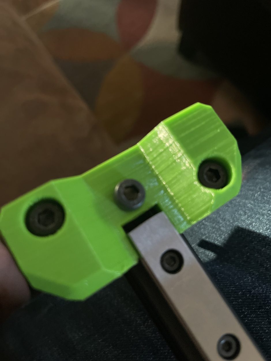
The rear bed arm is coupled to the bed via a Dual Access V-Pivot. This pivot allows the bed to rotate around the X axis (pitch) and Y axis (roll), yet fully constrains it from rotating around the Z axis (yaw). It is easiest to understand this by watching the video below.
There is little value in the constraining the rotation of the bed around the Z axis with the coupling between the bed arm and the bed, if the arm itself is still free to fractionally rotate at the linear rail junction due to clearances between the carriage (that the bed arm is attached to) and the linear rail. So, this must also be addressed.
To better constrain this, there are three obvious options that can be used in the 1P Z system to provide a stable linear motion system
1. The use of a lightly preloaded and much wider linear rail and carriage (Very expensive!).
2. The use of two large diameter widely spaced linear shafts. (Unfortunately, round bushings have bigger tolerances than linear carriages.)
3. The use of two widely spaced linear rails. (Needs careful alignment and possible precision machining of their mount.) In my case I mounted both rails 90 mm apart on a single 3090 extrusion. In hindsight it would have been easier to mount these near perfectly true to each other if I had milled the face of this perfectly flat before installing it in my printer. Luckily this is still easy to remove and do now.
And that’s it.
It is as simple as this
….and in engineering, simple is almost always best and best of all it is now impossible to have leadscrew induced artifacts in the prints.
Are there any downsides to the design?
Where the design has the potential to fail is in the quality and performance of the Dual Access Pivot. I am still working through a range of options for this. For the implementation to be successful it is critical that this pivot fully constrains rotation around the Z axis.
If you have any questions please feel free to ask.
Files for implementing this on a V-Core 3 300 are posted on thingiverse here:
https://www.thingiverse.com/thing:5519892
License information on the 1P Z system are here:
https://www.thingiverse.com/thing:5442000
License information of the Dual Axis V-Pivot are here:
https://www.thingiverse.com/thing:5475498